Death Stranding 2 Voxel Map Learning
Recently, I noticed that some materials from GDC 2026 had been released. As a big fan of the Death Stranding series, the first talk I wanted to study was “‘DEATH STRANDING 2’: Making of Voxel 3D UI Map” by Ildar Valeev. I tried to build a small demo using the techniques described in the talk. In this article, I will go over those techniques and discuss their benefits. Note that I don’t have access to the presentation video, so all the contents below are inferred from the slides.
Demo source code: Death Stranding Voxel Map
Overview
As many players know, Death Stranding 2 has an iconic 3D voxel UI map that players use to plan routes before each delivery. Compared to Death Stranding 1, the map is fully 3D this time, which makes the planning experience even better. Before diving into the implementation details, let’s look at the goals the development team had in mind:
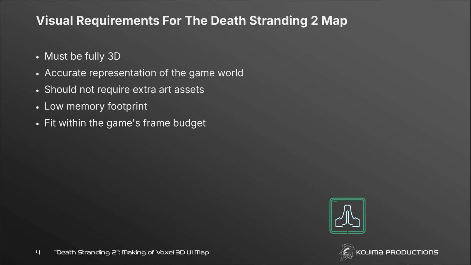
After looking at the first three points, you might have an idea about why they chose the voxel map: To have the fully 3D map and accurate representation at the same time, the most intuitive idea is to “downsample” the original assets, so that there will be no extra assets required while it can accurately reflect the terrain shape from the real assets.
Getting 3D Data from the Assets
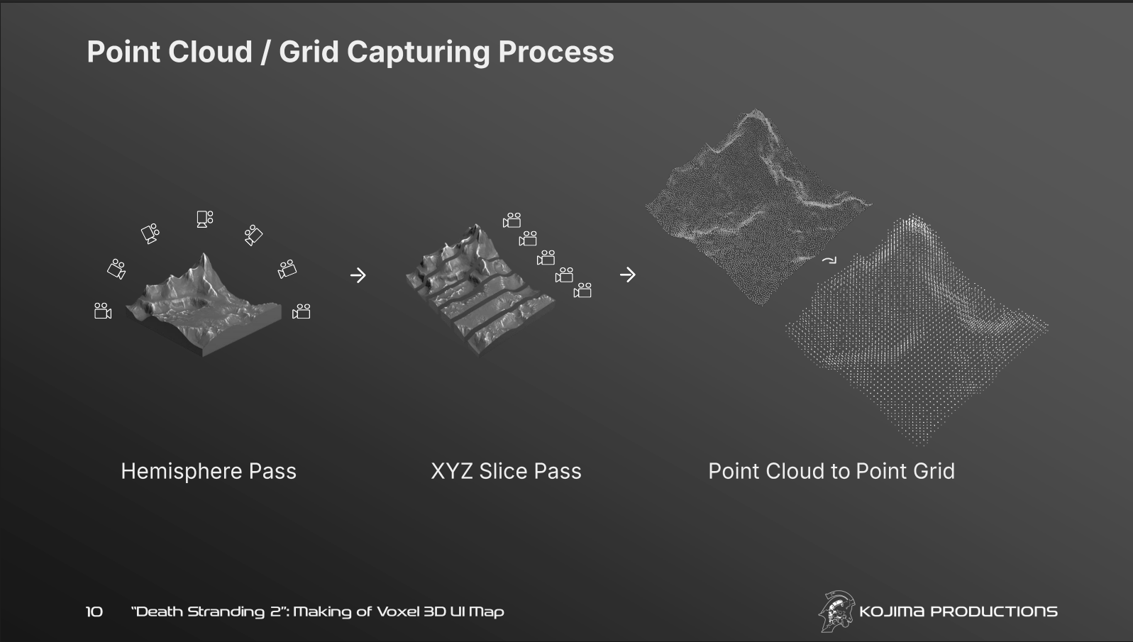
The development team used a preprocessing approach to capture the terrain and convert the captured data into a format suitable for voxel rendering, where they have multiple passes to render the terrain from different angles, including:
- Hemisphere Pass, which distributes the cameras along a hemisphere and look at the center of the terrain
- XYZ Slice Pass, which distributes the cameras along three axis to get “orthogonal” captures
After these passes, the captured points are converted into a uniform point grid, which is more suitable for voxel rendering.
Voxel Rendering
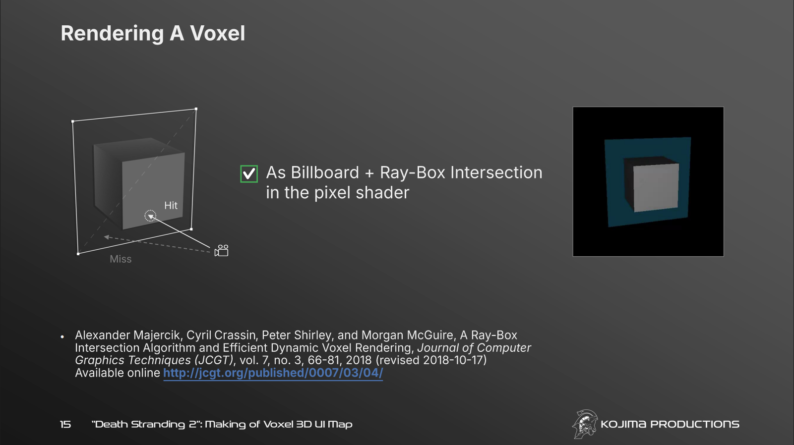
The entire map contains tens of millions of voxels, so it would be unrealistic to render each voxel as an actual mesh. This becomes even more challenging when the terrain can deform in certain scenarios, such as a voidout. Even rendering each voxel as a camera-facing half-cube mesh would still be too expensive. The clever solution is to render each voxel block as a billboard quad.
For each billboard quad, the shader performs a ray-box intersection test to reconstruct the actual voxel shape and discards pixels outside the voxel volume. In this way, we only pay for four vertices per block, while each block can represent up to 64 voxels. This successfully shifts much of the cost from the vertex stage to the fragment stage.
LOD
Once the number of rendered vertices is decoupled from the number of voxels, we can take the idea one step further: pack multiple voxels into a single billboard!
Instead of rendering one billboard per voxel, the team groups multiple voxels into a voxel block. Each voxel block is rendered as one billboard, and the shader uses the block data to decide what level of detail should be evaluated. This further reduces vertex pressure because one billboard can now represent an entire group of voxels instead of a single voxel.
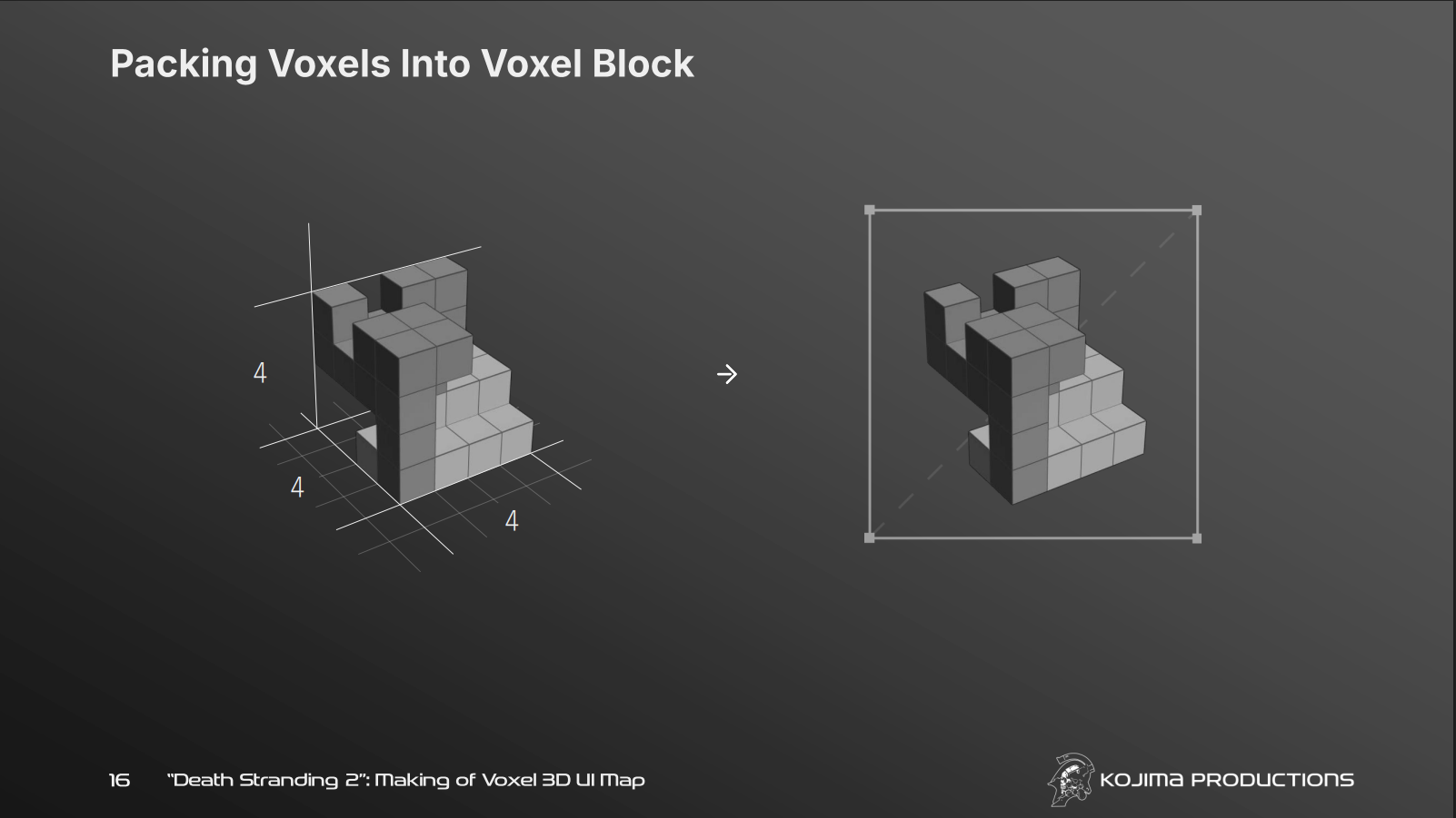
Another benefit is that blocks make LOD selection and transitions much easier. Depending on the distance from the camera, the shader can test the ray against different levels of the same block:
- Level 0: whole block bounding box
- Level 1: 2x2x2 coarse grid
- Level 2: 4x4x4 detailed voxel grid
When the block is far away, Level 0 is enough because the viewer cannot see the individual voxel details clearly. At a medium distance, Level 1 provides a rougher 2x2x2 shape. When the block is close to the camera, Level 2 evaluates the full 4x4x4 occupancy mask and determines which voxel the ray actually hits.
Demo Implementation
Now that we have walked through the main ideas behind the voxel map in Death Stranding 2, we can start implementing it in Unity! Let’s start from defining the data structures.
Voxel Data Structure
Here is how the world data is structured:
1
2
3
4
5
6
7
8
9
10
11
12
13
14
15
16
17
18
19
20
21
22
23
24
25
26
27
28
29
30
31
32
33
34
+-------------------------------------------------------------------+
|                        Q-PID REGION / WORLD                       |
+-------------------------------------------------------------------+
                                  |
                                  v
+-------------------------------------------------------------------+
|                              CHUNK                                |
|                                                                   |
|   +---------------+     +---------------+     +---------------+   |
|   |  Voxel Block  |     |  Voxel Block  |     |  Voxel Block  |   |
|   +---------------+     +---------------+     +---------------+   |
|   | (Smallest     |     |               |     |               |   |
|   |  Renderable)  |     |               |     |               |   |
|   +-------+-------+     +---------------+     +---------------+   |
+-----------|-------------------------------------------------------+
            |
            | Expands to 4x4x4 Grid (Up to 64 Voxels)
            v
        +---+---+---+---+
       /   /   /   /   /|
      +---+---+---+---+ +
     /   /   /   /   /|/|
    +---+---+---+---+ + +
   /   /   /   /   /|/|/|
  +---+---+---+---+ + + +
  |   |   |   |   |/|/|/|
  +---+---+---+---+ + + +
  |   | V |   |   |/|/|/|  --->  [ Single Voxel (V) ]
  +---+---+---+---+ + + +        +------------------+
  |   |   |   |   |/|/|/         | Properties:      |
  +---+---+---+---+ +            | * Color          |
  |   |   |   |   |/             | * Roughness      |
  +---+---+---+---+              +------------------+
- The world is divided into several chunks, which are grouped by Q-Pid region.
- Each chunk contains many voxel blocks, and a voxel block is the smallest renderable unit.
- Each voxel block contains up to 64 voxels in a 4x4x4 grid. Each voxel can have its own properties, such as color and roughness.
Choosing a 4x4x4 layout is a smart decision because the occupancy of one voxel block can be represented by a single 64-bit mask.
Based on this structure, we need two main data buffers: a per-block shape data buffer for ray-box intersection, and a per-voxel render data buffer for rendering information. Note that only existing voxels are stored in the render data buffer, which greatly reduces memory usage.
Per-Block Shape Data Buffer
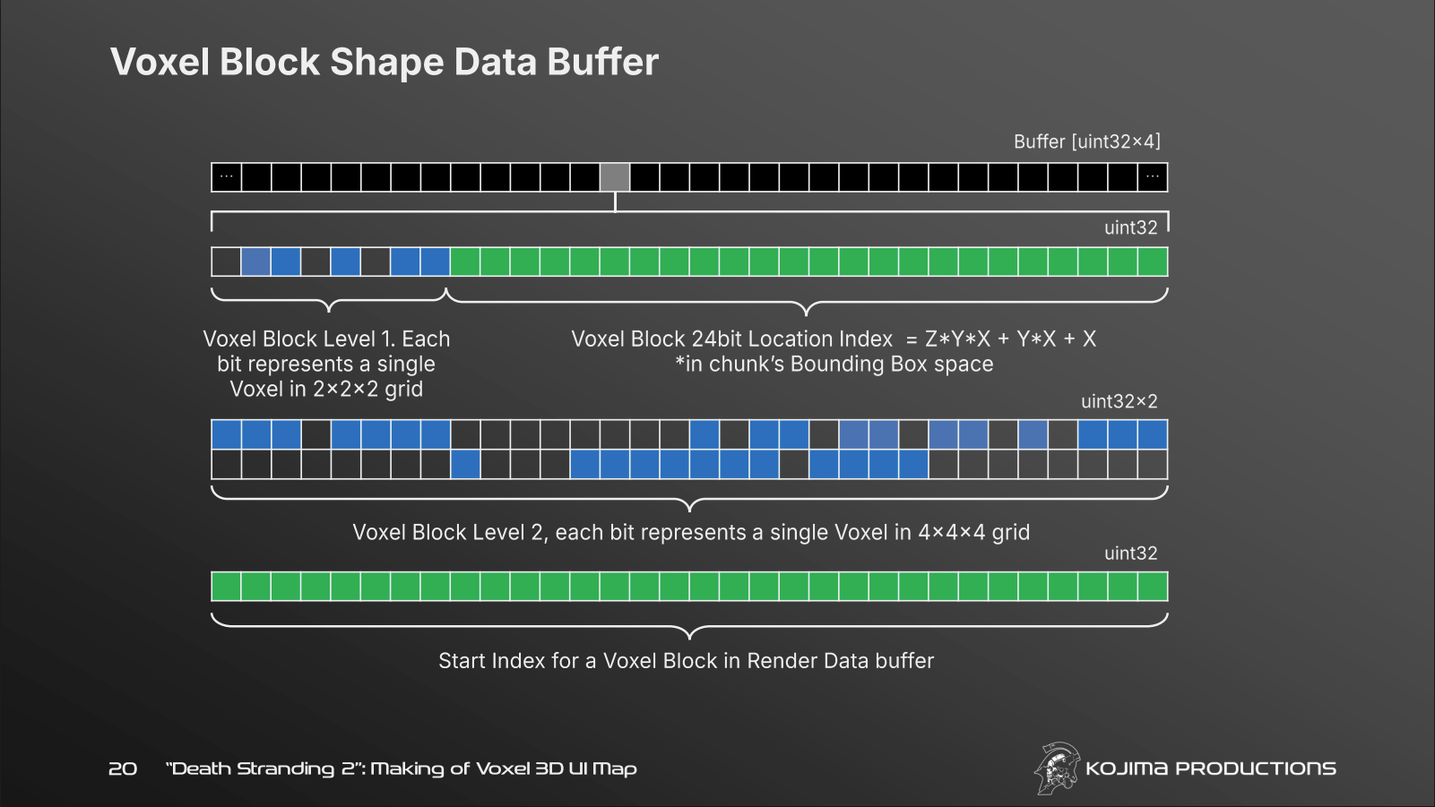
We pack each voxel block into four 32-bit integers. The interesting part is that we do not only store the detailed shape mask for the 4x4x4 voxel block, but also reserve 8 bits to describe the occupancy of a coarser 2x2x2 grid. This makes LOD selection and transition much easier to handle in the shader.
1
2
3
4
5
6
7
struct BlockRenderData
{
    uint shapeLevelAndLocation;
    uint shapeMaskLow;
    uint shapeMaskHigh;
    uint renderStartIndex;
};
shapeLevelAndLocation: The first 8 bits describe the occupancy of the 2x2x2 coarse grid, and the remaining bits store the block’s local location indexshapeMaskLowandshapeMaskHigh: These two integers provide 64 bits in total, describing the occupancy of the 4x4x4 voxel blockrenderStartIndex: The start index of this block in the render data buffer. The shader uses the block’s renderStartIndex plus the number of occupied voxels before the hit voxel in the shape mask to find the correct VoxelRenderData. For example,renderData[renderStartIndex + 1]retrieves the render data of the second occupied voxel in this block
Per-Voxel Render Data Buffer
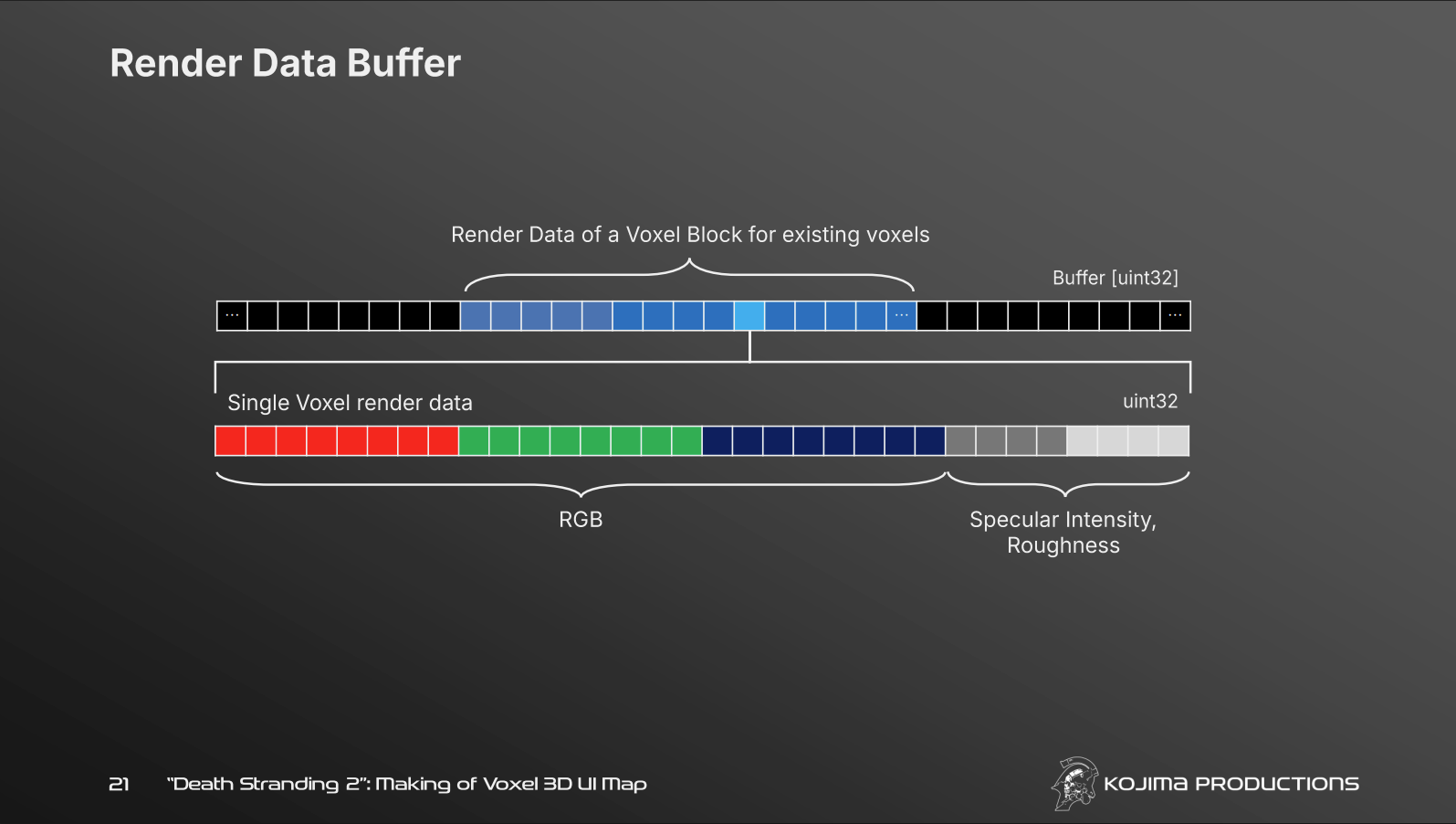
This part is simpler. We pack all the rendering information into a single 32-bit integer.
1
2
3
4
struct VoxelRenderData
{
    uint packedData;
};
In my demo, the packing is the same as the one in the slide above:
- RGB: 24 bits
- material/extra: 8 bits
Terrain Data Generation
Now that the data structures are defined, the next step is to generate some terrain data for the renderer. In the original presentation, the team captured the actual game world by scanning assets from different directions and converting the result into a point grid. For this demo, I wanted to focus more on the voxel rendering technique itself, so I used a simpler data generation pipeline.
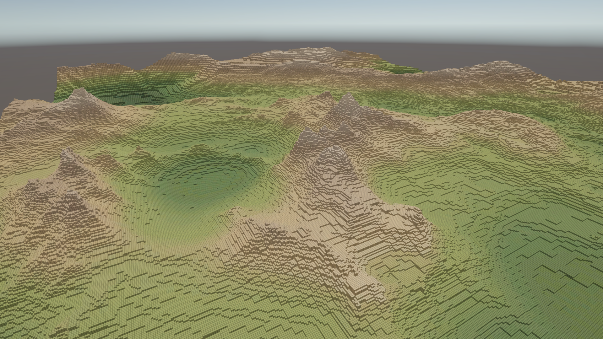
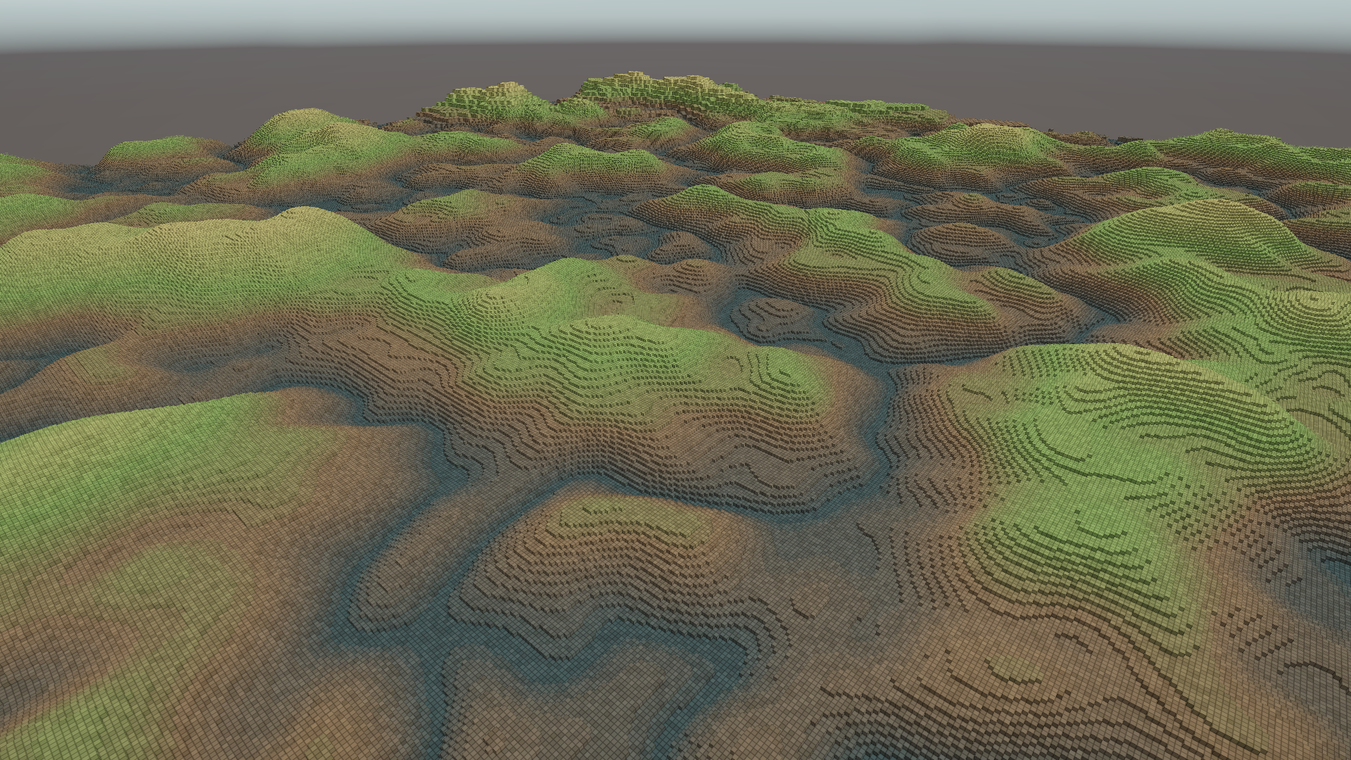
In my implementation, there are two terrain sources: height map terrain and procedural terrain. For the height map mode, the user provides a height map and a matching color map. The height map determines the voxel height, while the color map provides the per-voxel color data. For the procedural mode, the terrain is generated from noise functions, so the user can experiment with different noise types and parameters without preparing texture assets.
Height map terrain:
Procedural terrain:
Although the input sources are different, both paths eventually produce the same kind of voxel data. Conceptually, the process is:
- Sample the terrain source
- Convert each sample into one or more voxel positions
- Group voxels into 4x4x4 voxel blocks
- Build the shape data buffer and render data buffer used by the shader
To reduce this cost, I use Unity’s Job System together with Burst for the procedural generation path. Each (x, z) terrain sample is independent, which makes it a good fit for IJobParallelFor. Instead of generating voxels one by one on the main thread, the job distributes the sampling work across worker threads. Each job index maps to one terrain coordinate, evaluates the selected noise function, applies optional effects such as the crater deformation, and writes the resulting voxel positions into a native container.
The simplified logic looks like this:
1
2
3
4
5
6
7
8
9
10
11
12
13
14
15
16
17
18
19
20
21
22
[BurstCompile]
struct ProceduralVoxelGenerationJob : IJobParallelFor
{
    public int2 MapSize;
    public float3 MapScale;
    public int ShellDepth;
    public NativeParallelHashSet<int3>.ParallelWriter Voxels;

    public void Execute(int index)
    {
        int x = index % MapSize.x;
        int z = index / MapSize.x;

        float height = SampleHeight(x, z);

        for (int layer = 0; layer < ShellDepth; layer++)
        {
            int3 voxel = ConvertToVoxelCoord(x, z, height, layer);
            Voxels.Add(voxel);
        }
    }
}
After the raw voxel positions are generated, I build the voxel block map. Each voxel is converted into a block coordinate and a local bit inside that block. Note that all of the data containers here are the native ones. Like NativeParallelHashSet<int3> instead of HashSet<Vector3Int>. We only convert it back to the normal one when all the processing is done and it’s ready for uploading to the GPU.
Voxel Rendering
With all the data ready, now we can pass them into the shader and render the voxels!
At this point, the renderer provides two structured buffers:
BlockRenderData: one entry per voxel block. It stores the block location, LOD occupancy masks, the detailed 4x4x4 shape mask, and the start index into the render data buffer.VoxelRenderData: one entry per occupied voxel. It stores the packed material data, such as color, roughness, and specular intensity.
As we mentioned before, we render all the blocks as billboards, and we do Graphics.DrawMeshInstancedProcedural as below:
1
2
3
4
5
6
7
8
9
10
_blockDataBuffer.SetData(blockData);
_voxelRenderDataBuffer.SetData(voxelRenderData);

Graphics.DrawMeshInstancedProcedural(
    _quadMesh,
    0,
    _material,
    _renderBounds,
    _blockCount,
    _propertyBlock);
Vertex Shader
The vertex shader only needs the per-block data. It uses the instance ID to read one BlockRenderData entry, decodes the block’s location from shapeLevelAndLocation, and reconstructs the block bounds in world space.
After the block bounds are known, the shader expands a simple quad around the block center using the camera’s right and up vectors. This keeps the quad parallel to the screen and large enough to cover the projected voxel block. The quad itself is still flat, but the fragment shader will later reconstruct the actual voxel shape inside it.
The simplified logic looks like this:
1
2
3
4
5
6
7
8
9
10
11
12
13
14
15
16
17
18
19
20
21
22
23
24
StructuredBuffer<BlockRenderData> BlockDataBuffer;

Function VertexShader(VertexInput input):
    // 1. Fetch base data for the current Voxel block
    blockData = BlockDataBuffer[input.InstanceID]
    blockBounds = ReconstructBlockBounds(blockData.shapeLevelAndLocation)

    // 2. Handle reveal animation (e.g., emerging from the ground)
    progress = CalculateAnimationProgress(blockBounds.Center, effectCenter)
    if (AnimationEnabled):
        blockBounds.Y += CalculateRiseAndBounceOffset(progress)

    // 3. Billboard expansion
    // Expand the vertex towards the camera's "Right" and "Up" vectors to cover the 3D block
    billboardSize = blockBounds.Size * 3
    worldPos = blockBounds.Center
             + (CameraRightVector * input.LocalX * billboardSize)
             + (CameraUpVector * input.LocalY * billboardSize)

    // 4. Space transformation and data passing
    screenClipPos = TransformToClipSpace(worldPos)

    // Pass necessary data to the Fragment Shader
    Output screenClipPos, worldPos, blockBounds, input.InstanceID as BlockIndex
The important point is that the vertex shader does not know about individual voxels. It only reconstructs the block position and creates a screen-facing area where the fragment shader can perform the real voxel test.
Fragment Shader
The fragment shader is where the packed voxel data is actually interpreted, so it is more compute-intensive. For each pixel on the billboard, the shader creates a ray from the camera to the pixel position, then tests that ray against the voxel block.
The selected LOD controls how much of the block data is evaluated:
- Level 0 uses the whole block bounding box.
- Level 1 uses the 2x2x2 coarse occupancy stored in
shapeLevelAndLocation. - Level 2 uses the full 4x4x4 occupancy stored in
shapeMaskLowandshapeMaskHigh.
Once the shader finds a hit, it needs to fetch the correct material data. Since the render data buffer only stores occupied voxels, the shader counts how many occupied voxels appear before the hit voxel in the 4x4x4 mask, then adds that offset to renderStartIndex.
The simplified fragment shader flow looks like this:
1
2
3
4
5
6
7
8
9
10
11
12
13
14
15
16
17
18
19
20
21
22
23
24
25
26
27
28
29
30
31
32
33
34
35
36
37
38
39
40
41
42
43
44
StructuredBuffer<BlockRenderData> BlockDataBuffer;
StructuredBuffer<VoxelRenderData> VoxelRenderDataBuffer;

Function FragmentShader(PixelInput input):
    // 1. Setup & Early Culling
    ray = CreateRayFromCamera(input.WorldPos)
    blockData = BlockDataBuffer[input.BlockIndex]
    blockBounds = ReconstructBlockBounds(blockData.shapeLevelAndLocation)

    // 2. Ray Traversal
    lodLevel = DetermineLOD(DistanceToCamera)
    hitResult = TraceBlock(
        ray,
        blockBounds,
        blockData.shapeLevelAndLocation,
        blockData.shapeMaskLow,
        blockData.shapeMaskHigh,
        lodLevel
    )

    if (not hitResult.IsHit):
        Discard()

    // 3. Get Hit Voxel Offset
    occupiedVoxelOffset = CountOccupiedVoxelsBefore(
        blockData.shapeMaskLow,
        blockData.shapeMaskHigh,
        hitResult.LocalVoxelIndex
    )
    voxelData = VoxelRenderDataBuffer[
        blockData.renderStartIndex + occupiedVoxelOffset
    ]

    // 4. Depth Override
    Output.Depth = CalculateTrueDepth(hitResult.WorldPosition)

    // 5. Material & Shading
    material = DecodeVoxelMaterial(voxelData.packedData)
    ambientOcclusion = CalculateVoxelAO(blockData, hitResult)

    finalColor = CalculateLighting(material, ambientOcclusion, SceneLights)

    // 6. Output
    Output finalColor, Output.Depth
Because the actual mesh is only a flat billboard, the shader must also override the depth buffer with the true depth of the intersected voxel.
For the Level 2 traversal, I use the 3D DDA algorithm to efficiently walk through the 4x4x4 voxel grid. Instead of testing every voxel in the block, DDA advances from cell to cell along the ray and stops as soon as it finds the first occupied voxel or exits the block. Please refer to this link for more details.
Results
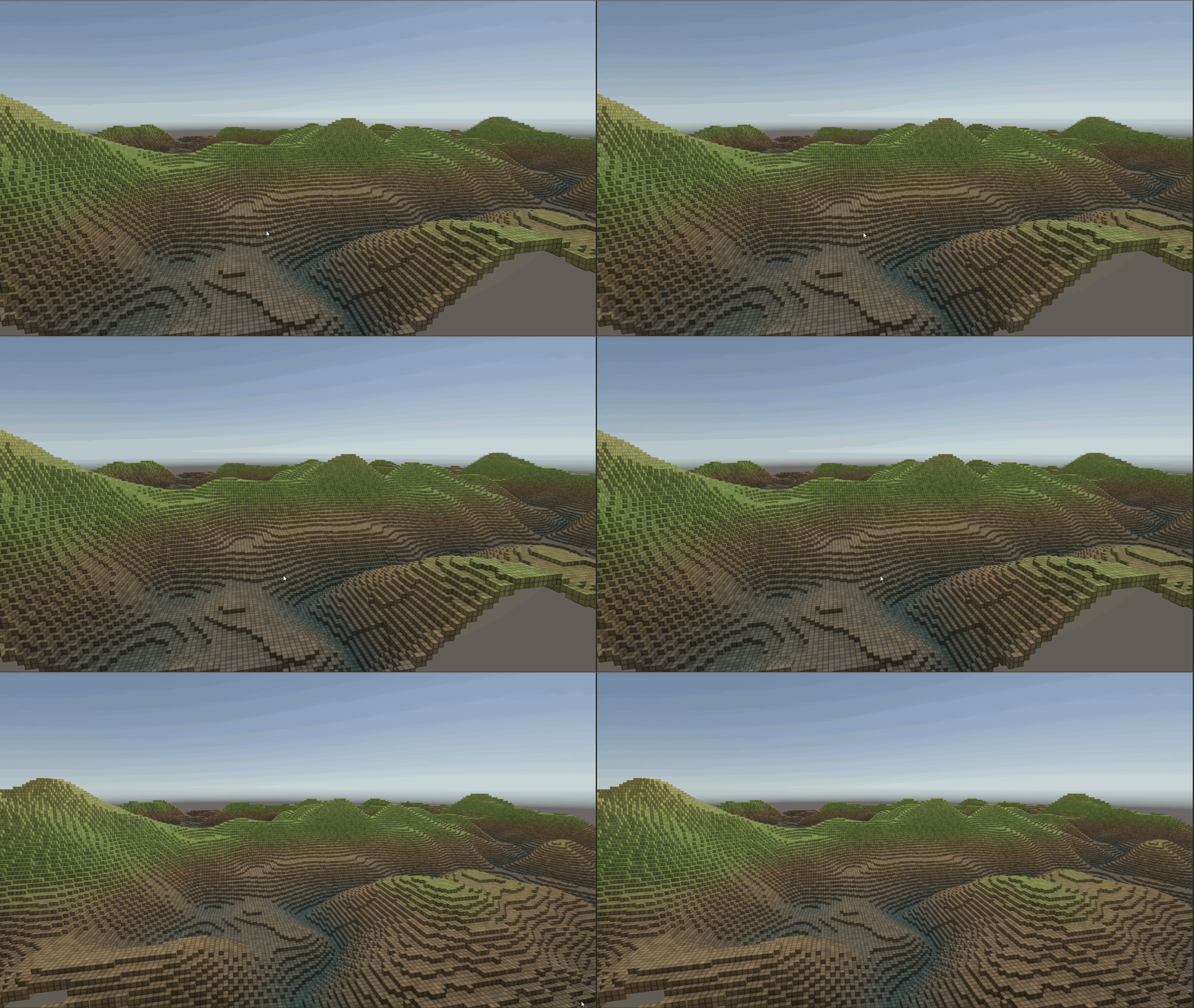
Finally, the 3D voxel map is working!
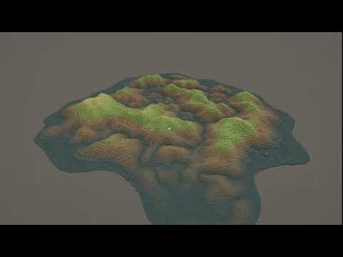
For a terrain space of roughly 2048x2048x256 voxels, the demo can run at more than 100 FPS steadily on my GTX 1080 at Full HD.
Additional Effects
After the core rendering pipeline was working, I started experimenting with a few additional effects.
Crater Effects
This effect is inspired by the voidout crater from the game. We can specify the crater’s XZ position, radius, blend width, and depth, then lower the terrain around that area.
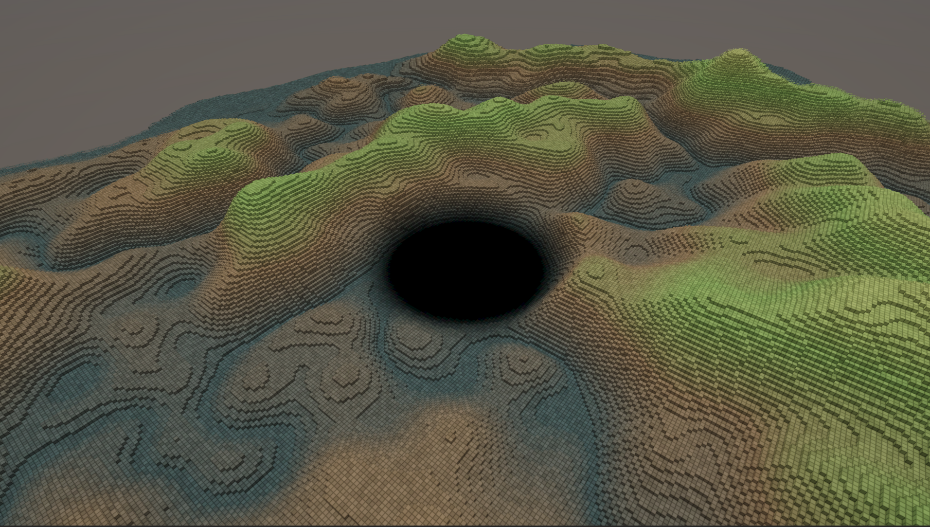
It is important to add a smooth transition around the crater boundary so the deformation blends naturally into the surrounding terrain.
Reveal Animation
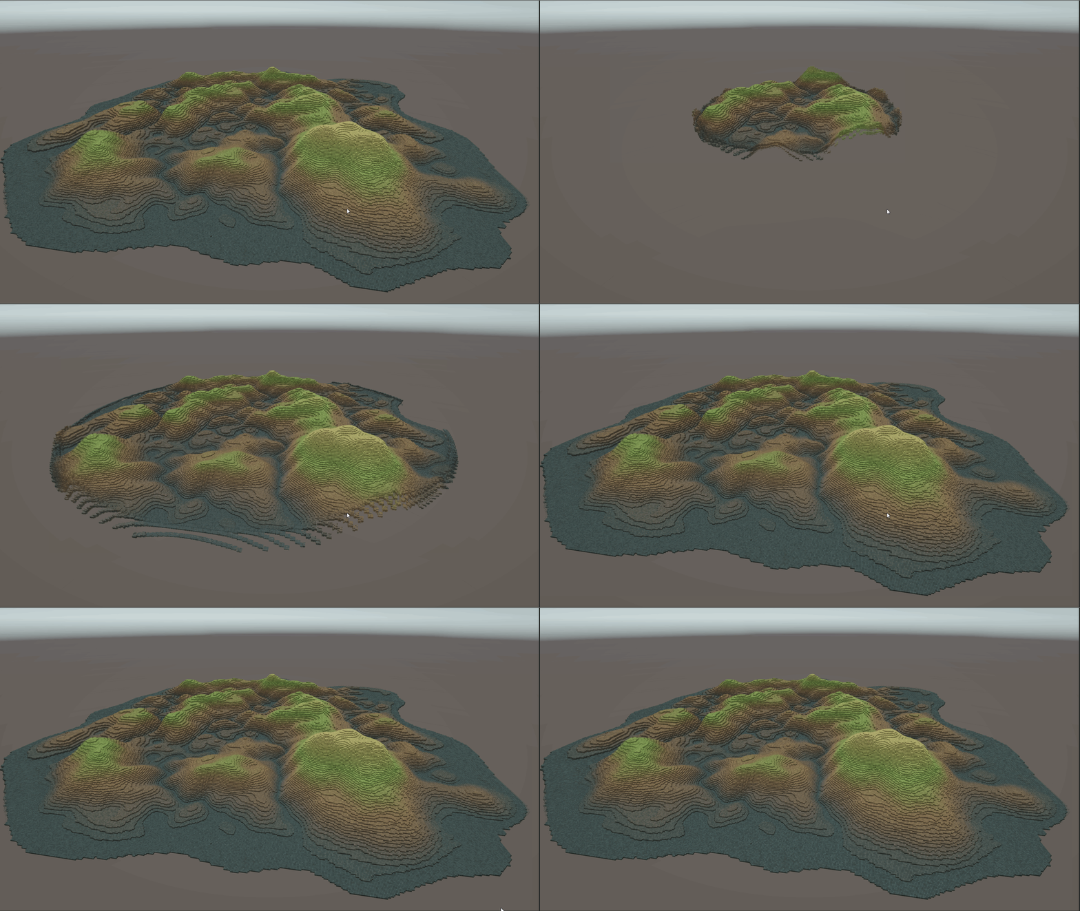
I also added a reveal animation that makes the voxel map appear outward from a given starting point. The shader evaluates each block’s distance from the reveal center, then uses that distance to decide whether the block should be hidden, rising, or fully visible.
Shape Mask
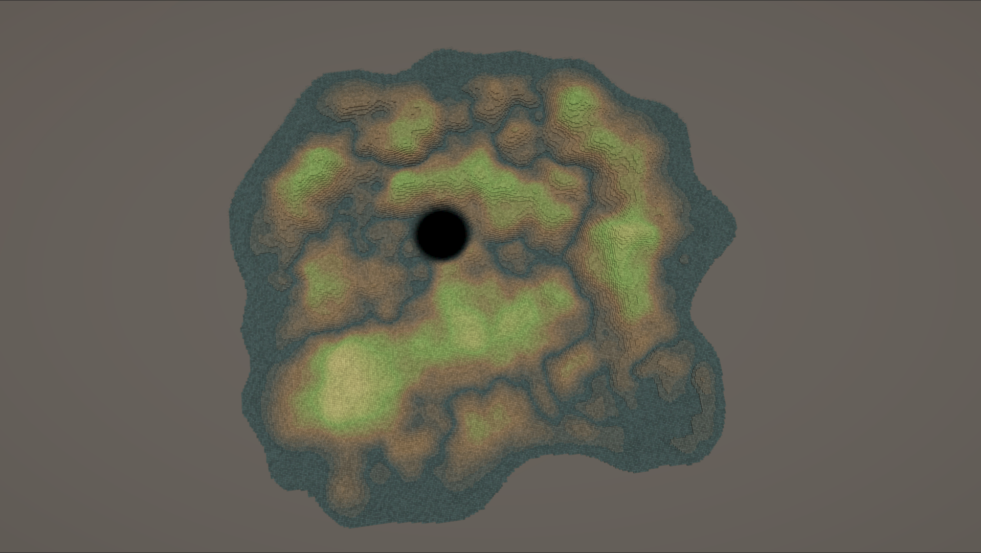
I added a shape mask during terrain generation so the terrain does not always end up as a rectangle. This makes the result feel more like a real terrain map.
LOD Transition Dithering
To make LOD transitions less abrupt, I experimented with a dithering effect. However, after testing it, I found that dithering might not be a good fit for voxel rendering. Finding a better way to handle LOD transitions for voxels would be an interesting topic to investigate further.
Boundary Fade-Out Effect
If you look closely at the voxel map in Death Stranding 2, you can notice that voxels near the camera seem to shrink before disappearing as the camera moves closer. In my current implementation, the voxels simply pop away. My guess is that this is related to the LOD transition mentioned above. Their transition may include a voxel shrink behavior, which also helps close-range culling look smoother.
Future Work
Build Time Optimization
- Use a sort-and-reduce pipeline to make block aggregation more parallel-friendly and further accelerate render data build time.
GPU Frustum Culling
- Consider doing GPU frustum culling for quads outside the view frustum to reduce unnecessary draws.